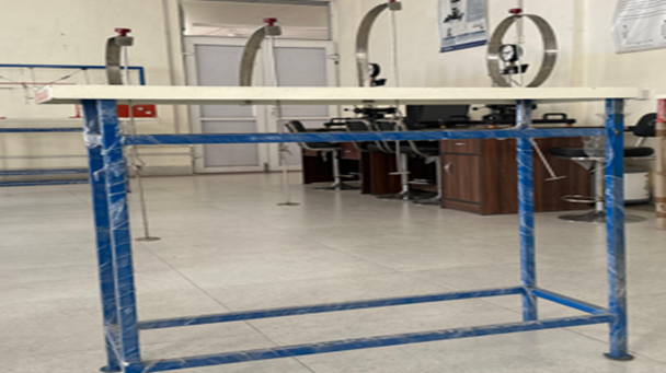
Three Hinged Arch
The Three Hinges Arch Experiment is a classic structural engineering experiment that demonstrates the behaviour and load distribution in an arch with three hinges under various loading conditions.
Objective
The primary objective of the Three Hinges Arch Experiment is to:
1. Understand the structural behavior of a three-hinged arch.
2. Analyze the effect of loads on the internal moments, axial forces, and reactions in the arch structure.
3. Demonstrate the equilibrium conditions and load-transfer mechanisms in statically determinate arches.
4. Explore the influence of different load positions on the structural behavior of the arch.
Description of the Experiment
A model of the three-hinged arch, often made from materials like steel or aluminum, is mounted on a testing frame. The arch has hinges at the two ends (supports) and at the crown. The two end hinges (supports) can be a fixed hinge (pinned support) and a roller hinge to allow free horizontal movement, simulating the real-life behavior of arches under load. Loads can be applied at various points along the arch, either at the crown, quarter-span, or at random points. These loads can be concentrated loads or distributed loads, depending on the objectives of the experiment.
Measuring Instruments
Dial Gauges: To measure deflection and deformation of the arch at various points.
-
Load Cells: For measuring the magnitude of loads applied
-
Strain Gauges: Placed at strategic points to measure the stress and strain distribution within the arch.
-
Hinges: The three hinges at each support and at the crown allow rotation, reducing internal stresses and making the arch statically determinate.
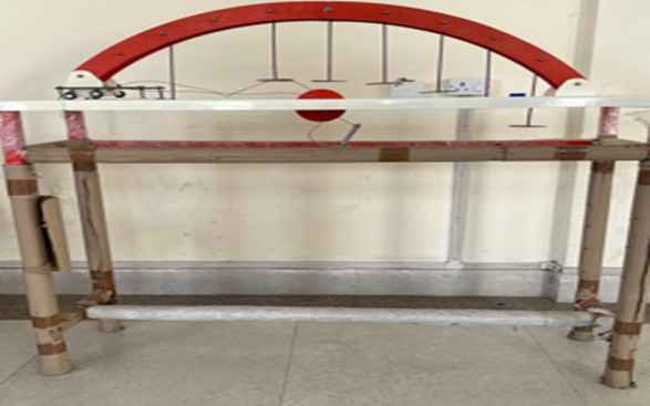
Pin Joint Truss Experiment
The Pin Joint Truss Experiment is a fundamental structural engineering test used to study the behavior of pin-jointed trusses under various loading conditions. Pin-jointed trusses are commonly used structural elements in bridges, towers, and roofs, where they efficiently bear loads through axial forces.
Objective
The primary objectives of the Pin Joint Truss Experiment are to:
-
Understand the load distribution in a pin-jointed truss.
-
Identify the nature of forces in truss members (tensile or compressive).
-
Apply equilibrium equations to analyze the force in each member.
-
Verify the theoretical calculations for internal forces within the truss members.
Description of the Experimental Setup
-
Truss Structure: A model truss, typically a Pratt or Warren truss, is used in the experiment. The truss is made of slender members connected by pins (joints) that allow rotation, idealizing each joint as a hinge and enabling axial force transmission without bending.
-
Support Conditions: The truss is supported on a fixed pin at one end and a roller at the other end to simulate real-life truss supports. The fixed pin restricts both vertical and horizontal movement, while the roller support allows horizontal displacement to accommodate expansion or contraction.
-
Loading Mechanism: point load is applied at specific joints, such as the top or bottom nodes of the truss. This load simulates typical external load acting on the truss. Loads can be applied incrementally and at various points to analyse different loading conditions and their impact on member forces.
-
Measuring Instruments: Load Cells: Measure the magnitude of applied loads. Strain Gauges: Attached to truss members to measure axial strains, which can be used to calculate internal forces. Dial Gauges or Deflection Gauges: Measure deflections of nodes to verify theoretical assumptions of no bending in ideal truss members.
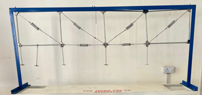
Column Buckling Experiment
The Column Buckling Experiment (also known as the Euler Buckling Experiment) is designed to study the stability of slender columns under axial loads and to observe the phenomenon of buckling.
Objective
The main objectives of the Column Buckling Experiment are to:
-
Investigate the buckling behavior of a column under axial compressive loads.
-
Determine the critical load (buckling load) at which the column loses stability.
-
Understand the relationship between the column length, cross-sectional area, end conditions, and buckling load.
Description of the Experiment
-
Column Specimens: Slender, straight columns of different lengths and cross-sections are used. The columns can be made of materials like steel, aluminum, or wood, and are often of circular or rectangular cross-sections. The length-to-diameter (or slenderness) ratio is selected to ensure the columns are prone to buckling rather than failing due to material strength.
-
Support Conditions:
-
The column ends can be arranged with different boundary conditions such as pinned-pinned, fixed-fixed, pinned-fixed, or free-fixed, as these significantly influence the buckling load.
-
Commonly, pinned-pinned (both ends pinned, allowing rotation) is used to simulate ideal boundary conditions for simple calculations.
-
Loading Mechanism:
-
An axial compressive load is applied to the column gradually using a loading frame or hydraulic loading device.
-
The load can be increased incrementally, with readings taken at each increment to observe when the column begins to buckle.
-
Measuring Instruments: Load Cell: To measure the applied compressive force on the column. Dial Gauges: Placed at various points along the column to measure lateral deflection as buckling occurs.

Two Hinged Arch
The Two-Hinged Arch Experiment is an important test in structural engineering that examines the behaviour of a two-hinged arch under various loading conditions. Unlike three-hinged arches, which are statically determinate, two-hinged arches are statically indeterminate to the first degree.
Objectives
The primary objectives of the Two-Hinged Arch Experiment are to:
-
Study the load distribution and structural behavior of a two-hinged arch under different load conditions.
-
Determine the reactions and internal forces within the arch.
-
Understand how the arch resists bending moments, axial forces, and horizontal thrusts.
-
Investigate how changes in load location and magnitude affect the stability and deformation of the arch.
Description of the Experimental Setup
-
Arch Structure: A model of a two-hinged arch, typically made of steel or aluminum, is mounted within a test frame. The arch’s shape can be parabolic or semicircular, designed to span between two pinned supports. The arch’s profile and material properties are chosen to emphasize bending, axial forces, and deformations.
-
Support Conditions: The two-hinged arch has hinges at both ends, which act as pinned supports. These supports can rotate but do not allow horizontal or vertical movement of the ends, creating a fixed span for the arch. Unlike a three-hinged arch, the two-hinged arch does not have a hinge at the crown, making it statically indeterminate.
-
Loading Mechanism: Loads are applied incrementally at different points along the arch, such as at the crown, quarter-span, or random points, to analyze varying load distributions. Loads can be applied as point loads or distributed loads, depending on the objectives of the experiment.
-
Measuring Instruments: Dial Gauges: Used to measure deflections and deformations at various points along the arch. Load Cells: Record the exact amount of load applied to the arch. Strain Gauges: Placed on the arch’s surface at strategic points to measure stress and strain distribution within the arch.
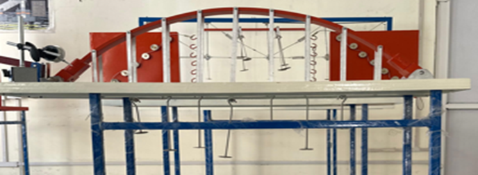
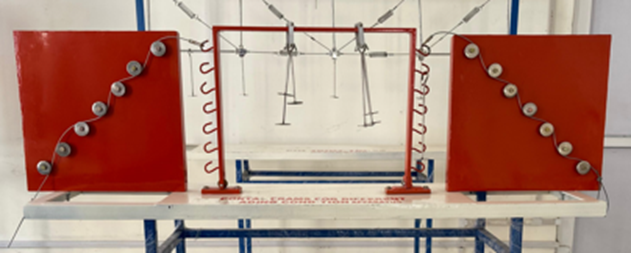
Portal Frame For Different Load Conditions
The Portal Frame for Different Loading Conditions Apparatus experiment is used to study the behaviour of portal frames under various loading conditions, including point loads, distributed loads, and eccentric loads.
Objectives
The main objectives of the portal frame experiment are to:
-
Analyse the behaviour of portal frames under different loading conditions.
-
Determine the deflection, bending moments, and shear forces in the frame members.
-
Understand the frame's response to vertical and lateral (horizontal) loads.
-
Explore the influence of load magnitude and location on stability, strength, and deformation of the frame.
Description of the Experimental Setup
-
Portal Frame Model: A model portal frame, typically made of materials like aluminum or steel, is used. The frame generally has a rectangular or square shape, with two vertical columns connected by a horizontal beam. The frame geometry and dimensions are chosen to represent real-life structural configurations in portal frame buildings.
-
Support Conditions: The base of the frame is fixed, meaning it is restrained from movement and rotation. This fixed support mimics the real-life attachment of a frame to a foundation. The fixed supports provide stability against lateral movement, ensuring that any deflection or deformation occurs primarily within the frame itself rather than at the supports.
-
Loading Mechanism: Vertical Point Load: Applied at specific locations on the horizontal beam, usually at the centre or one-third span, to simulate gravity loads acting downward. Horizontal Point Load: Applied to the top of the frame columns or at the mid-span to simulate wind or other lateral loads. Eccentric Load: A load applied at an off-centre point along the horizontal beam to create asymmetrical loading conditions. Distributed Load: Applied uniformly along the length of the beam to simulate distributed weight, such as a roof load or snow load.
Deflection of Curved Members Apparatus
The Deflection of Curved Member Apparatus Experiment is conducted to study the behavior of curved structural elements under applied loads. Curved members are commonly used in arches, frames, and various architectural structures where curved elements provide stability, aesthetic value, and efficient load transfer.
Objectives
The main objectives of the Deflection of Curved Member Apparatus Experiment are to:
-
Analyze the deflection behavior of curved members under various loading conditions.
-
Determine the effect of member curvature on deflection and stress distribution.
-
Compare experimental deflection with theoretical predictions.
-
Understand how load position and magnitude influence the structural response of curved members.
Description of the Experimental Setup
-
Curved Member: A curved member (often a semicircular or quarter-circular arc) made of steel, aluminum, or another flexible material is mounted on the apparatus. The geometry, thickness, and material properties are chosen to allow observable deflection under applied loads while being resistant enough to prevent material failure.
-
Support Conditions: The curved member is fixed or pinned at specific points (typically at the ends), depending on the structure’s design. Commonly, one end is fixed while the other end allows rotation to simulate real-world conditions, such as those found in arches and curved beams in construction.
-
Loading Mechanism: Loads are applied vertically at different points along the curved member’s arc, including the apex and quarter-points, to simulate various load distributions. Point loads, or incremental loads, are commonly used to understand the response at specific positions along the curve.
-
Measuring Instruments: Dial Gauges: Placed at key points along the curved member to measure vertical deflections due to loading. Load Cells: Measure the magnitude of the load applied at each loading point. Strain Gauges: Sometimes used at critical locations to measure stress distribution in response to the applied load.
