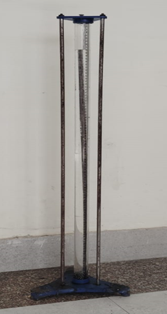
Bernoulli’s Apparatus
Technical Specifications:
Flow channel: 350 mm length, made of acrylic conduit
Peizometer tubes: 9 Nos. Placed equal spaced at 5 cm mounted on graduated board
Constant head tank: 1 No. Size (300mm x 300mm x 450mm), Capacity 30 litres
Measuring tank: 300mm x 300mm x 300mm
Sump tank: 600mm x 300mm x 300mm, Capacity 60 litres
Pipings and fittings: GI material used
Valves: 2 Nos. For drain, 1 No. For water control, 1 No. For bypass
Stop watch: Electronic
Pump: 0.5 HP single phase, 220 VAC + 10% CG make
Power requirement: 220 VAC + 10%, 50 Hz
Learning Objectives:
The primary objective of Bernuolli’s experiment is to investigate the validity of the Bernoulli equation when it is applied to a steady flow of water through a tapered duct.
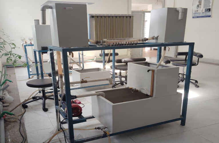
Reynold’s Apparatus
Technical Specifications:
Tube: Clear acrylic 800 mm length, 32 mm outer diameter and 25 mm inner diameter
Dye vessel: Material- Stainless steel, 1 litre capacity
Constant head tank: 1 No. Size (300mm x 300mm x 450mm), Capacity 30 litres
Measuring tank: 300mm x 300mm x 300mm
Sump tank: 600mm x 300mm x 300mm, Capacity 60 litres
Pipings and fittings: GI material used
Valves: 2 Nos. For drain, 1 No. For water control, 1 No. For bypass
Stop watch: Electronic
Pump: 0.5 HP single phase, 220 VAC + 10% (ISI)
Setup fitted on angle iron frame of size 1280mm x 330mm x 910mm
Power requirement: 220 VAC + 10%, 50 Hz
Learning Objectives:
The primary objectives of Reynold’s experiment are:

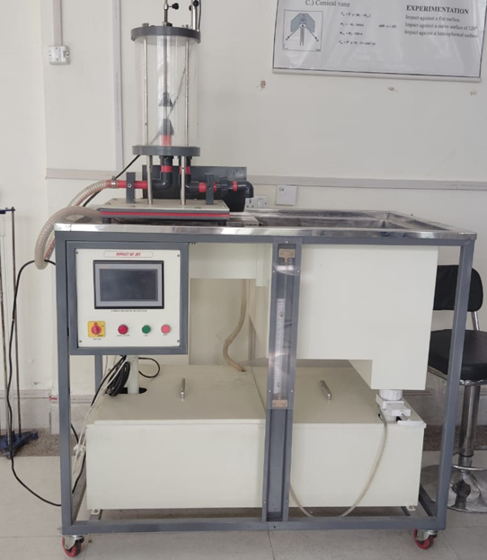
Impact of Jet Apparatus
Technical Specifications:
Net dimensions and weight: 740 mm high x 420 mm wide x 310 mm and 6 kg
Approximate packed dimensions and weight: 0.176 m3 and 13 kg
Flat plate: 74 mm diameter, normal to and coincident with the jet axis
Hemispherical plate: 60 mm diameter
Conical plate: 75 mm diameter, 120°
Angled plate: 75 mm diameter, 30°
Ancillaries (included): All necessary pipe clips and tubing
Power requirement: 220 VAC + 10%, 50 Hz
Learning Objectives:
The primary objectives of the impact of jet apparatus are:
-
To investigate the reaction forces produced by the change in momentum of a fluid flow when a jet of water strikes a flat plate or a curved surface, and
-
To compare the results from this experiment with the computed forces by applying the momentum equation.
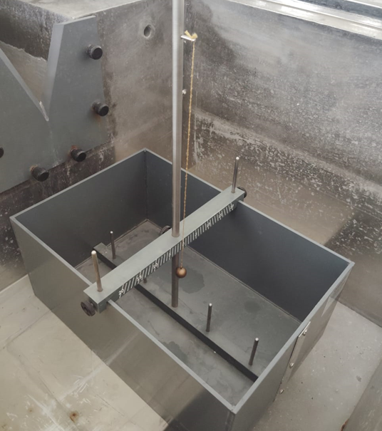
Metacentric Height Apparatus
Technical Specifications:
Net dimensions: 170 mm x 380 mm x 250 mm with a horizontal guide bar for aliding weight.
Water tank: Size 600 x 400 x 400 mm (Approx.)
Distance from pontoon centre line to added weight: 123 mm
Centre of gravity of pontoon: 125 mm approx. from outer surface of vessel base
Weight of vessel: 3 kg approx.
Height of mast loading position above water surface of vessel base: 790 mm
Max. angle of heel: ±130
A set of weights is supplied with the apparatus
Learning Objectives:
The primary objectives of the metacentric height apparatus are:
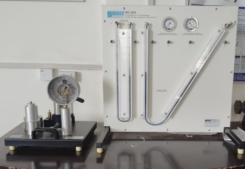
Pressure Measurement Devices
Technical Specifications:
Inclined tube manometer angle: 30°
Measuring ranges: 0 - 500mmWC (U-tube manometer)
0 - 500mmWC (inclined tube manometer)
0 - ±60mbar (Bourdon tube pressure gauge)
Dimensions: 750mm x 610mm x 810mm (LxWxH)
Calibration device: 410mm x 410mm x 410mm (LxWxH)
Total weight: approx. 40 kg
Learning Objectives:
The primary objectives of these pressure measurement devices are:
i) Direct method with U-tube manometer and inclined tube manometer
ii) Indirect method with Bourdon tube pressure gauge
Flow Measurement Devices
Technical Specifications:
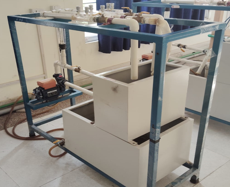
Venturimeter: Material – Clear acrylic, 2.54 cm diameter pipe
Orifice meter: Material – Clear acrylic, 2.54 cm diameter pipe
Water circulation: FHP pump, Crompton/ Sharp make
Flow measurement: Using measuring tank, Capacity 30 litres
Sump tank: Capacity 50 litres
Stop watch: Electronic
Electricity supply: Single phase, 220 VAC, 50 Hz.
Learning Objectives:
The primary objectives of the flow measurement devices are:
-
To determine the coefficient of discharge through venturimeter and orifice meter
-
To measure discharge through venturimeter and orifice meter, and
-
To obtain the relationship between Reynolds number and the coefficient of discharge.
Falling Ball Viscometer
Technical Specifications:
Viscosity Range: 0.5 - 7x10⁴ mPa-s (cP)
Falling Time-Lower Limit: 60 s for Ball No.1
30 s for Ball Nos. 2,3,4,5 and 6
Falling Time-Upper limit: 300 s
Materials with viscosity>7x10⁴ mPa-s require running time of over 300 s.
Measuring Distance: 100 mm (50 mm between adjacent ring marks) in both directions
Fall Tube Inner Diameter: 15.94mm ± 0.01mm
Set of Balls: 6 balls
Working Angle: KF30: 80° (DIN position); KF40: 80°, 70°, 60°, 50°
Temperature Range: -5°C - +150°C
Sample Volume: 40 mL
Learning Objectives:
The primary objectives of the falling ball viscometer are:
-
To determine the density of a sphere
-
To determine the density and viscosity of an unknown fluid.
-
To determine the uncertainty in the density and viscosity measurements
-
To identify any discrepancies within the experimental results and provide a plausible explanation for the observed discrepancies.
